RS and RKO rules: practical application
AIS: fault alarms and the radar display
AIS targets on the radar display help operators monitor traffic. However, sending targets to the radar is only one part of an installation. Access to the AIS controls and the required audible fault alarm must be addressed separately. These issues are easily overlooked when an enquiry discusses only the interface and the number of targets displayed.
Which clauses concern the AIS itself?
This guide is based on clauses 3.4.9.1–3.4.9.4 of Part V, Navigation Equipment, of the RS Rules for the Equipment of Sea-Going Ships. Under clause 1.1.1, this Part applies to self-propelled ships not engaged on international voyages. For other operating conditions, the applicable framework must be established separately. Instructions from the flag State maritime administration are taken into account under clause 1.1.3 and take precedence in the event of a conflict.
Clause 3.4.9.1 requires the AIS display and controls to be conveniently located in the wheelhouse. Clause 3.4.9.2 permits individual units that do not require operational control to be installed in an equipment room or a dedicated cabinet near the wheelhouse. This does not mean that the operating panel may be enclosed in a cabinet with the other electronics.
Clause 3.4.9.3 connects the AIS fault-relay output contacts to an audible signalling device. This may be the AIS built-in loudspeaker, an external device or the bridge alarm system. These are alternative implementations; the list does not require three independent audible devices to be installed together.
Radar data and AIS fault alarms: two separate signal paths
In the first signal path, AIS data reaches the radar and targets are displayed. In the second, an equipment fault triggers the required alarm. Targets appearing on screen demonstrate a particular data-exchange function; they do not, by themselves, establish that the fault relay is connected or that the alarm is audible at the operating position.
The documentation should therefore show navigation-data transmission and the fault-alarm path separately. The latter needs the actual output assignment, a supported alarm-device configuration and a test method. A connection must not be selected merely because connector names look similar.
An example of real marine equipment
NSR NSI-1000 is presented by its manufacturer as a Class A marine AIS with separate transponder and display/control units. Listed data-exchange destinations include RADAR, ECDIS and BAM. This establishes the model's relevance to the task, but mentioning BAM does not demonstrate a ready-made connection to a particular bridge alarm system or the required physical contact in the selected version.
Before ordering, request current documentation for the units offered and separate details of the fault output and alarm devices. If the existing alarm system is retained, its designation, documentation and available-input details are also needed. A working connection is established through an agreed wiring diagram and testing, rather than a list of interfaces in promotional material.
What to include in the installation schedule
| Item | Question to resolve |
|---|---|
| AIS Indicator and Control | Are they conveniently located for operation in the wheelhouse? |
| Units not requiring operational control | Where are they located and how are they serviced? |
| Fault output and alarm | How is the audible-alarm circuit connected and tested? |
| Transmission of data to radar | Which actual interfaces and settings are provided? |
| Pilot computer connection | Is the connection point near the pilot's working position? |
The last row concerns the separate requirement in clause 3.4.9.4. It does not mean that every optional cable listed in a catalogue automatically forms part of the mandatory supply. Connection details and package contents must be established from the design and documentation.
In your enquiry, specify the vessel type and class, existing AIS and radar, alarm-system configuration, photographs of the stations, cables to be retained and work required. This allows the quotation to distinguish equipment replacement, data exchange and alarm testing.
Sources
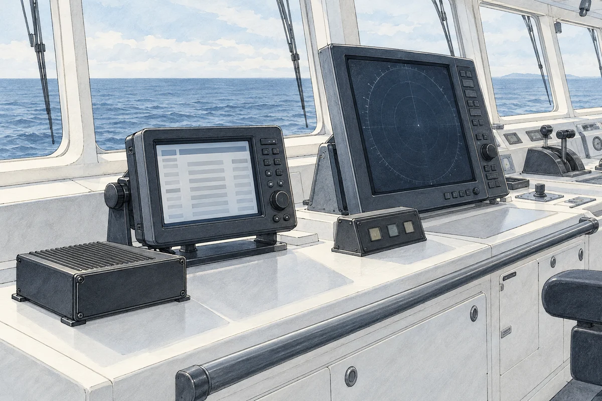
Requirements: the official Part V of the RS Rules, clauses 1.1.1–1.1.3 and 3.4.9.1–3.4.9.4. Model application: Official page of NSR NSI-1000. The illustration shows the functional separation schematically and is not a wiring diagram.