RS and RKO rules: practical application
Radar display: visibility and access to controls
When replacing a radar, checking the new screen diagonal and available console cut-out is insufficient. The watchkeeper needs a clear sea horizon, a readable radar image and access to controls at the same time. A separate control panel can help organise the station, but its position must be considered together with every station displaying radar information.
Which siting requirement applies?
This guide is based on clause 3.4.6.1 of Part V, Navigation Equipment, of the RS Rules for the Equipment of Sea-Going Ships. Clause 1.1.1 limits the scope of this Part to self-propelled ships not engaged on international voyages. Applicability to another vessel must be established separately. Additional flag State maritime-administration instructions are taken into account under clause 1.1.3 and take precedence in the event of conflict.
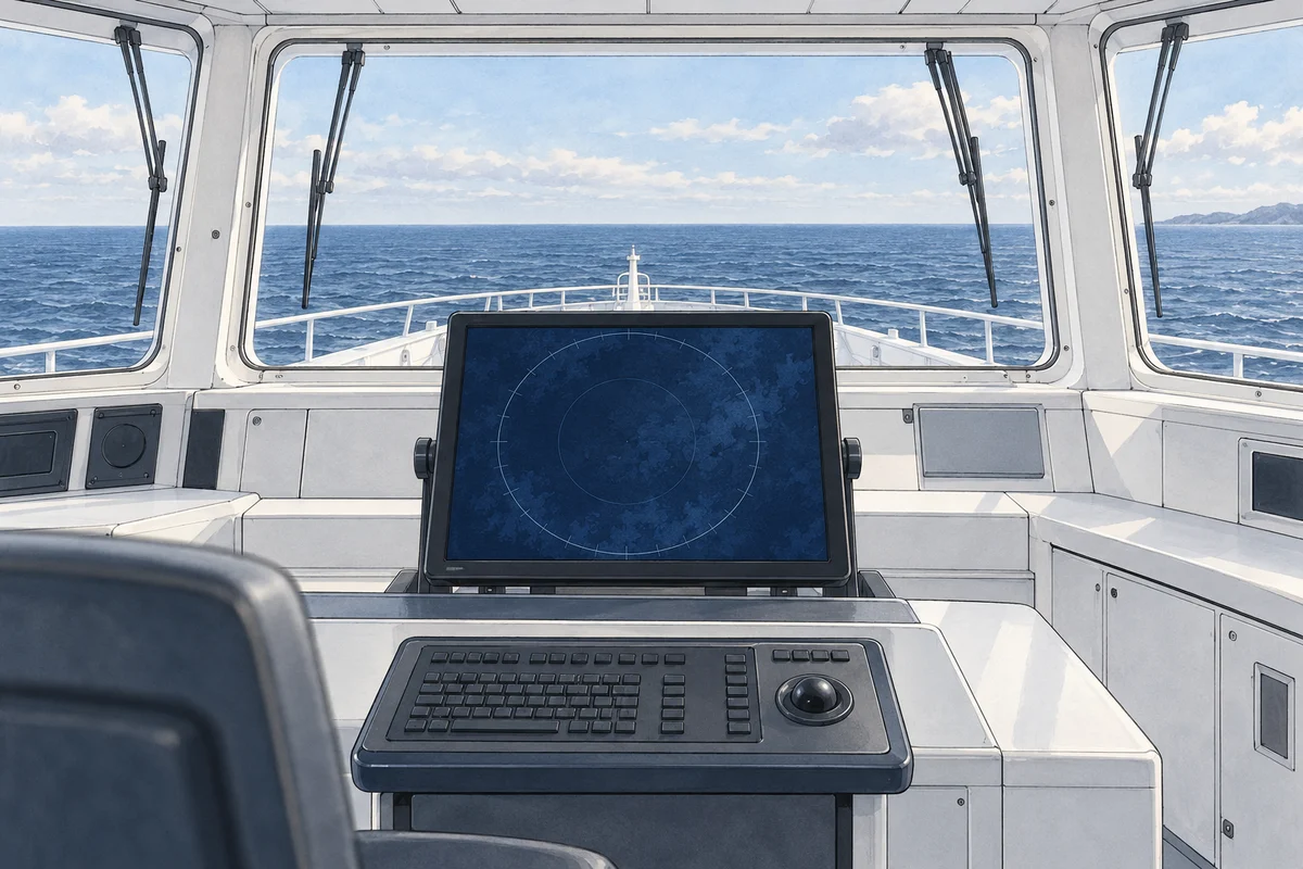
Clause 3.4.6.1 provides for the main display to be located near the forward bulkhead of the navigation bridge. It must not obstruct visual observation ahead. Lighting must not impair the image. Locating an additional display near the chartwork position is recommended. That recommendation must not be recast as an unconditional obligation to install a second screen on every vessel.
What changes with a separate control panel?
Where controls are separate from the display, the rule requires control from each working position at which radar information is displayed. The design must therefore be assessed station by station: which screen the operator sees and where the radar can be controlled. An available video output alone does not resolve this issue.
For example, KODEN MDC-7912P is classified by its manufacturer as a marine radar. The version with a 19-inch display has a separate control unit. This provides a real example for discussing a separated layout, but does not establish that arbitrary cable lengths, any repeater or a particular remote-control arrangement are acceptable. The design needs documentation for the exact version selected and its component units.
How to check the place before making the console
First mark the operating positions and forward sightlines on the drawing. Consider the normal watchkeeping position, window frames, console height, other instruments and intended display tilt. A screen that fits the cut-out can still obstruct an important part of the view with its housing or bracket.
Then assess daylight, light fittings and reflections under actual bridge conditions: bright daylight, twilight and night lighting. Brightness adjustment is useful but cannot eliminate glare from a poorly positioned window. Shading and light placement must be chosen for the vessel; the clause gives no universal installation dimension.
Finally, list all stations displaying radar information. Identify the operating display, additional displays and each station's purpose separately. Use this layout to check control access and manufacturer restrictions, rather than merely counting connected screens.
Information to provide for a quotation
| Data | Why is it necessary? |
|---|---|
| Vessel type, operating area and class | Identify the applicable regulatory framework |
| Bridge plan, photo and size of console | Check sightlines, housing clearance and control-panel access |
| List of work stations and screens | Establish where management is required |
| Existing radar and units to be retained | Establish the actual replacement scope |
| Lighting conditions and cable routes | Clarify layout and version-specific restrictions |
The quotation should distinguish supply of the display, control panel and specified connections from work to assess placement. Version approval and installation acceptance must be considered separately from the display diagonal.
Sources and scope of this guide
Sources: the official Part V of the RS Rules1.1.1–1.1.3 and 3.4.6.1; role and composition of the model the manufacturer's KODEN MDC-7912P page. The illustration explains the task of placement and does not serve as an installation scheme.