RS and RKO rules: practical application
GNSS receiver/display at the chartwork position
Receiving position data and using it conveniently at a working position are different issues. A new GNSS instrument may send data to the network while located far from where chartwork is performed. Its own display location must therefore be considered alongside the actual bridge workflow.
Requirement in clause 3.4.10
The basis is clause 3.4.10 of Part V, Navigation Equipment, of the RS Rules for the Equipment of Sea-Going Ships, edition 01.01.2026. This Part defines an electronic position-fixing system. The receiver/display of such a system must be located immediately near the chartwork position.
Under clause 1.1.1, this Part covers self-propelled ships not engaged on international voyages. Establish the applicable framework for other operating conditions separately. In the event of conflict, apply additional flag-administration instructions under clause 1.1.3.
This clause gives no universal distance in centimetres. The design must show the actual working position and receiver/display location relative to it. Data availability at another instrument does not by itself establish compliance with the receiver/display siting requirement.
An actual GNSS instrument example
NSR NGR-3000 is presented by its manufacturer as marine GNSS equipment with its own navigation-data display. The rev15.2 brochure describes the main instrument and separate antenna, data outputs and BAM/INS connections. Confirm actual package contents and version separately for the order.
NGR-3000 provides position and other satellite-navigation data. It must not be described as a gyrocompass or automatically treated as a replacement for a true-heading sensor. If other instruments receive its data, establish the data purpose and actual interface for each consumer.
Assessing the working position
Mark the chartwork position, receiver/display and passage between them on the bridge plan. Check that information is accessible during actual operation, rather than merely visible from the other side of the wheelhouse. Consider operating modes, operator position, lighting and access to controls under the instrument documentation.
Consider main-unit placement and antenna-location selection separately. A conveniently installed display does not establish sky visibility at the antenna, and a suitable antenna does not resolve the working-position arrangement. Both must belong to one agreed configuration.
Schedule before replacing a position source
| Information | Purpose of the information |
|---|---|
| Vessel, design, class and operating area | Establish the scope of applicable requirements |
| Chartwork-position plan | Check receiver/display location |
| Receiver to be retained and new supply contents | Establish the actual replacement boundary |
| List of position-data consumers | Check required data and interfaces |
| Antenna, cable and power supply | Identify the remaining installation components |
Attach working-position photographs and connection diagrams to the enquiry. Ask for separate descriptions of instrument supply, relocation or layout modification, and post-installation checks. A touchscreen or three data outputs does not replace assessment of the actual installation.
Sources
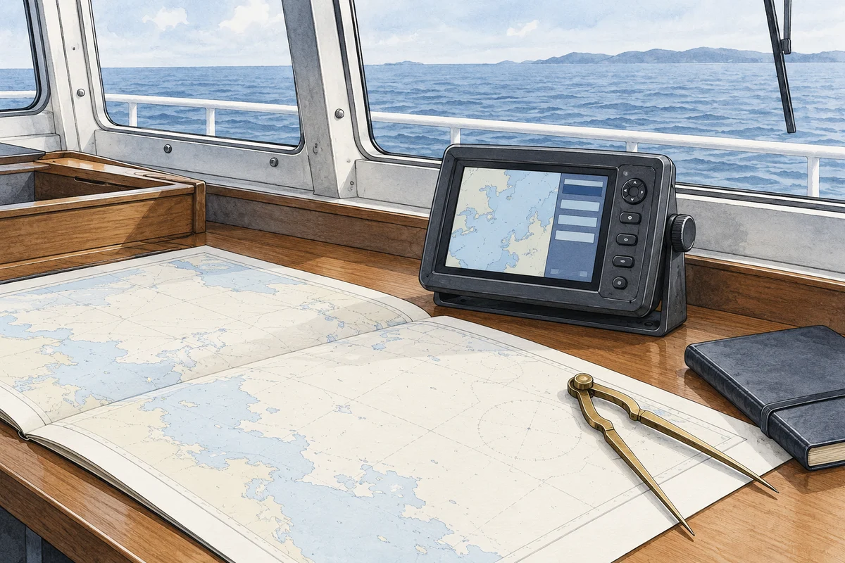
The official Part V of the RS Rules: clauses 1.1.1–1.1.3, the electronic position-fixing system definition and 3.4.10. Model function and configuration: the official NSR page and rev15.2 brochure. The illustration is schematic and shows neither a particular NGR-3000 version nor an approved layout.