RS and RKO rules: practical application
Navigation-equipment earthing: checking the complete connection chain
When replacing a radar, preserve more than its supply cable and data exchange. The new unit must form part of the specified earthing system, with incoming cable shields properly bonded. A working radar image does not establish the quality of these connections.
Four requirements of section 4.5
This is about clauses 4.5.1–4.5.4 of Part V, Navigation Equipment, of the RS Rules for the Equipment of Sea-Going Ships, edition 01.01.2026. Under clause 1.1.1, the scope is self-propelled ships not engaged on international voyages. Establish the regulatory framework for other operating areas separately. Under clause 1.1.3, flag-administration instructions take precedence in the event of conflict.
Clause 4.5.1 requires protective earthing of navigation equipment to the ship's hull by the shortest route. Clause 4.5.2 concerns cable shields: at entry into equipment they must be electrically connected to the hull. Under clause 4.5.3, radio-navigation instruments additionally require functional high-frequency earthing.
Clause 4.5.4 limits the total resistance of all electrical connections in any earthing path to 0.02 Ω. This requirement concerns the chain of connections, rather than one neat terminal or an isolated conductor section.
What can not be solved by appearance
A metal bracket does not establish reliable electrical contact with the ship's hull. Coatings, corrosion, unsuitable connections or modified parts may lie in the path. Likewise, a connected signal-cable shield does not by itself establish compliance with every protective and functional earthing requirement for the instrument.
During a survey, first establish the actual arrangement from documentation: the intended equipment connection points, the path to the hull and cable-shield bonds. Then check workmanship and the specified measurements. Do not substitute an arbitrary jumper to the nearest metal object without establishing its hull connection and the manufacturer's requirements.
Why you need to document a particular block
KODEN MDC-7912P is presented by its manufacturer as a marine radar. This makes it a relevant example for discussing navigation-equipment earthing. It does not, however, determine the connection points, conductor cross-section, material or construction for a particular installation on the designer's behalf.
A quotation requires installation instructions for the selected version, the unit list and information about the existing earthing system. Include retained equipment in the overall diagram. Consider protective and high-frequency functions separately, even if the design uses related structural components.
What to fix when replacing
| Survey material | Practical meaning |
|---|---|
| Diagram from the units to the hull | You can see the whole circuit of electrical connections. |
| Photos of points and contact status | You can determine the amount of recovery. |
| Block designations and input cables | Actual versions and cable shields are accounted for |
| Measurement procedure and test report | The result relates to a defined circuit |
| List of changes after installation | Documentation corresponds to the work done |
The low resistance limit requires a suitable measurement method and consideration of test-lead effects. Specialists must determine the method and safe work procedure from current documentation. A simple continuity indication is not equivalent to quantitative confirmation of 0.02 Ω.
Include the vessel, class, operating area, radar model, diagram and photographs of existing connections in the enquiry. Ask for survey, materials, installation, testing and recording of results to be itemised. This addresses the actual task rather than merely adding an unspecified 'earthing kit' to the order.
Sources and illustration
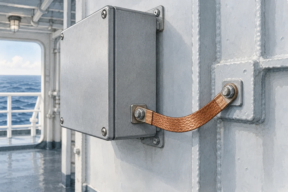
Basis -- the official Part V of the RS Rules1.1.1 to 1.1.3 and 4.5.1 to 4.5.4. The purpose of the model is the KODEN MDC-7912P page. The bonding-jumper illustration is schematic: it does not show a specific instrument, the complete earthing path or a verified measurement result.